

FEM / CFD / FSI - IMAGES
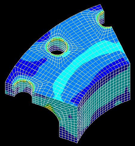
Shaft with shoulder (FEM-analysis, stress concentration, convergence).
Threaded combination (FEM-analysis, load-bearing capacity).
Mooring system (FEM-analysis, nonlinear transient dynamics).
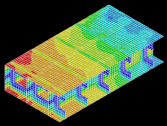
Buckling check of platform deck (FEM-analysis, eigenvalue).
"Built-in dry dock" exposed to wind loads (CFD / FEM / FSI - analyses).
Random vibration analysis of flare boom exposed to wind loads.
Substructuring and submodelling.
Return to the english edition of the home page.
Gå tilbake til den norske utgaven av hjemmesiden.
Images from numerical analyses performed by HL Engineering are presented on the present page. As mentioned on the homepage, we do also have extensive experience from conventional hand calculations, and from development of advanced analytical design formulas and design methods for special purposes.
Different types of analyses and different element types are used in the models in each section below (linear and nonlinear static and dynamic structural analyses using 3D-solids, axisymmetric solids, shell elements and beam elements - and fluid flow analyses using fluid elements).
The analyses were performed by using the FEM program system ANSYS and the CFD program system FLOTRAN.
The images were pasted from the ANSYS Display program to a drawing program at a resolution of 1024x768. The quality of the images may be poor if you use a lower resolution (but also note that the quality of the present type of images are of lower quality than the graphics in ANSYS).
HL Engineering hope you will enjoy the images, but as a matter of form, we want to point out that they should not be used for documentation, marketing or other purposes by other companies or persons. Unauthorized use, distribution or duplication is prohibited, and HL Engineering does not assume any responsibility for the validity, accuracy or applicability of methods or results.
Shaft with shoulder - stress concentration factor and convergence test
The present image from a simple, linear FEM-analysis show the stress concentration in a shaft with shoulder. In order to ensure that reliable analysis results are obtained (and not just "pretty pictures" are produced), HL Engineering have developed several analysis models for check of convergence for various element types and mesh densities.

Threaded combination - stripping strength
A few images from a nonlinear FEM-analysis of a threaded combination follows. The ultimate load-bearing capacity (stripping strength) is found by considering plasticity, large deflections and contact between the threads. Load / deflection graphs and plots (zooms) of the areas near the upper and lower threads in the pin/nut-structure are shown below.


Mooring system - nonlinear, dynamic analysis
A method for structural analyses of mooring systems in Ansys is under development and a "working method" has been established. Geometric nonlinearity, contact between mooring and seabed, hydrodynamic drag damping and structural damping is considered in the present model (nonlinear material behaviour can easily be included). The applied loads on the system are excitation forces (or motions) from the hydrodynamic analysis, wave drift forces and loads due wind, current, buoyancy and gravity. Nonlinear static and dynamic analyses are performed.
The following images show the resting position of the mooring system; deflection due to lateral loads and time-dependent response of typical nodes for a typical seastate. A similar approach can be used for analyses of flexible risers.


Buckling check of platform deck module
The present image is from a simple, linear FEM-analysis (eigenvalue buckling analysis for evaluation of slenderness).

"Built-in dry dock" exposed to wind loads - CFD / FEM / FSI - analysis
The present images are from an analysis of a "built-in dry dock" with an accordion type of door (the dimensions are significant - the building is 450 meters long and 150 meters wide). The analyses involved evaluation of fluid flow and pressure distribution on the door and the other building surfaces due to wind loads (CFD analysis using Ansys/Flotran - evaluation of various openings in the building); transfer of pressure to a FEM model for structural analyses of the door (Ansys), and evaluation of fluid/structure interaction (FSI).
The first image show particle flow traces (trajectories) near the building (partly open door to the left). The second and third images show pressure distribution and fluid velocity respectively near door and roof, while the last image show the deflection of the door (the images are from different runs with different amount of openings in the building).


![]()
Flare boom exposed to wind gusts - random vibration analysis
The following images show a flare boom (side view), the lowest natural vibration mode and the power spectral density (PSD) for a typical node. Several vibration modes are calculated and combined in accordance with the PSD combination method. The Ansys Parametric Design Language (APDL) is used to program the power spectrum of the fluctuating component of the drag force (i.e. load spectrum based on wind spectrum); load due to mean wind and routines for probabilistic analyses of peak response, gust factors, stress amplitudes and fatigue damage based on the 1-sigma displacement, velocity and acceleration solutions evaluated by Ansys. The 1-sigma displacement solution includes calculation of stresses, strains and forces in addition to displacements, while the 1-sigma velocity and acceleration solutions also include calculations of stress velocities, stress accelerations, etc.


Substructuring and submodeling
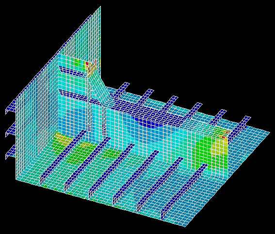
The following two images show a vessel (expanded solution for typical superelement and sideview of superelement assembly).


The following two images show a pipe structure (submodel of flange (solid elements) and model of pipe (shell elements)).


The following two images show a platform deck structure (submodel and part of global analysis model).


Last update: April 28, 1999